Toyota Land Cruiser FJ60 A/C System
When I bought my FJ60 the A/C was blowing really cold air. I mean freezing air. I didn't think too much of it until one hot day I had the A/C on in stop and go traffic. Suddenly the A/C air was warmer, and shortly after I smelled burning lining. The A/C compressor had jammed solid, and the clutch on the compressor axle was just spinning and burning.
A new compressor cost me $350, along with a $20 receiver/drier and $500 to have Gary's Auto install these, flush the R12 from the system, convert fittings to R134A, and refill with R134A. This is a pretty big outlay so I decided to check and make sure that the electronic control systems were operating correctly. They were not - the A/C compressor was never disengaging if the A/C button on the dash was depressed.
A quick check in the manual shows the schematic of the control circuit:
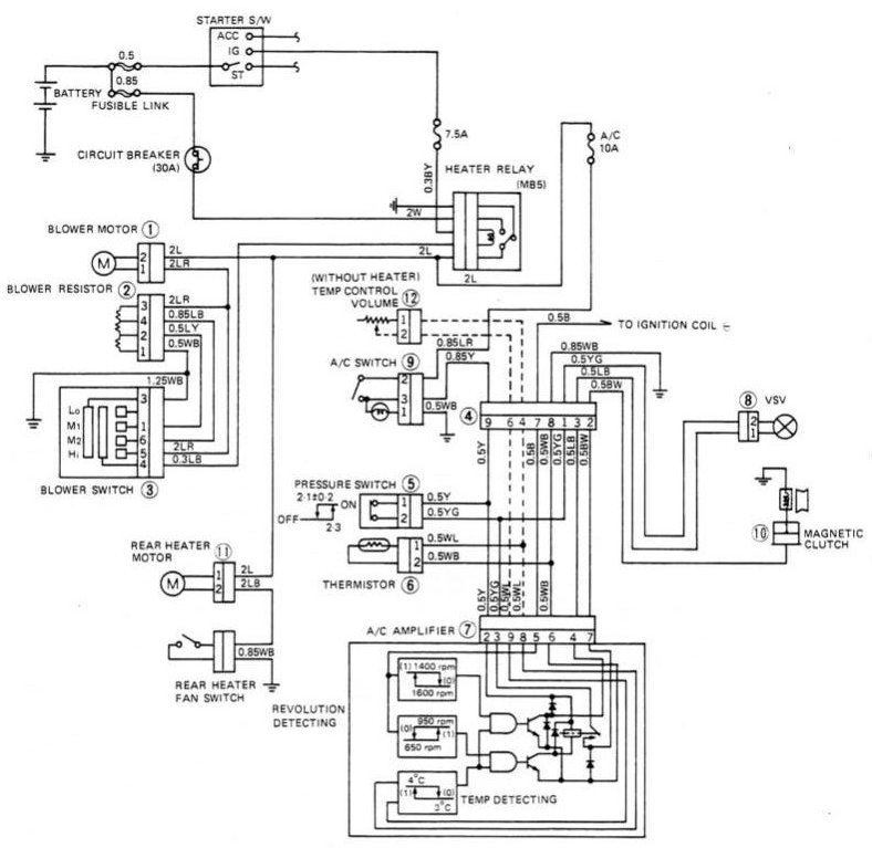
The logic is provided by the "A/C Amplifier" at the bottom of the schematic. This is a small PCB inside a plastic case located just under the passenger side dashboard. The 9 pins on the PCB are as follows:
| Pin | Function |
| 1 | NC |
| 2 | V+ 12VDC from A/C switch |
| 3 | V+ 12VDC switched by low pressure A/C - off if pressure less than 2.1 |
| 4 | Idle up VSV (output) |
| 5 | Ignition coil signal (input) |
| 6 | Chassis ground |
| 7 | Compressor magnetic clutch (output) |
| 8 | Evaporator Thermistor (input) |
| 9 | NC |
The pins can easily be seen on a front view of the amplifier board:
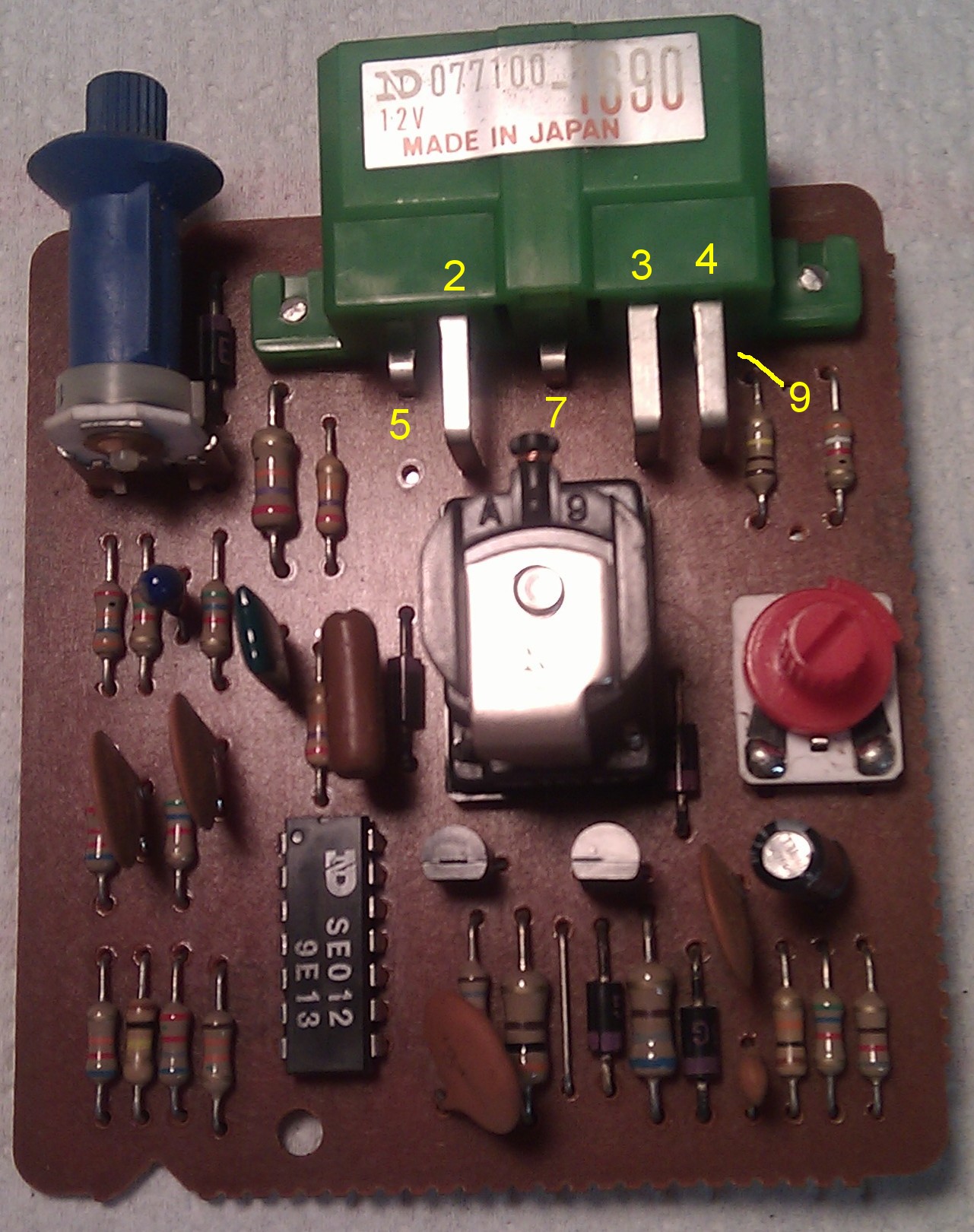
The blue knob protrudes through the plastic housing and is used to adjust the engine RPM at which the A/C amplifier will cut off the compressor on low idle, and also engage the compressor after idle-up is accomplished with the VSV. The red knob adjusts the temperature at the evaporator at which the compressor will be turned off to avoid evaporator freezing (factory target is about 34F).
By attaching a voltmeter between pins 6 and 8, you can monitor the voltage drop across the thermistor. On mine, the voltage ranges from about 1.5V (80F ambient) to around 2.1V at 32F when the evaporator begins to freeze. By measuring this I could see that the thermistor was properly measuring the temperature of the evaporator. But the compressor just stayed engaged at all times, even after freezing occurred.
I adjusted the red knob and was able to switch the VSV on/off as the amplifier attempted to turn off the system, but the clutch never disengaged - pin 7 remained high telling the compressor to run. Left as is, this would burn out my new compressor.
I pulled the amplifier all the way out and examined it more closely. Lo and behold here is what I found on the reverse side of the PCB:
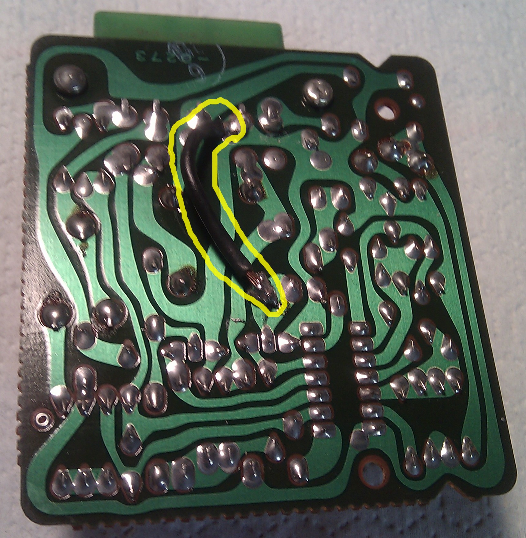
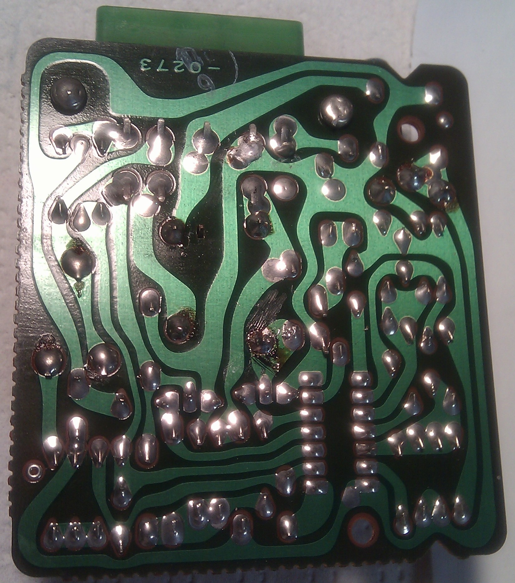
Somebody had modified the board, adding a jumper (circled in yellow above). The jumper connects the collector of the switching transistor to V+, engaging the clutch relay (middle of the PCB) at all times. I removed the jumper and the system began to work somewhat as intended, cycling the clutch. Here's what the back of the PCB should look like, without the jumper:
Since I had disturbed the red and blue knobs, I needed a procedure to adjust them. Here's what I came up with, since the manual doesn't tell you how to adjust the red knob:
- Turn the blue knob fully CCW, and set the red knob to midway.
- Run the engine with doors closed, windows up, and A/C on recirculate, low fan speed. If the compressor does not engage, slowly turn the red knob CW until you hear idle up (engine RPM goes to 900 or so) and the compressor engages.
- Open the hood, and look at the lines going to the compressor. The compressor should disengage before the return line begins to form frost on the outside. Turn the red knob CCW to disengage the clutch when the temperature is still too high to form frost. This may take patience while you adjust a bit at a time, wait for a few cycles, and adjust again.
- Once the red knob is set OK, turn the blue knob CW a bit at a time, listening for the compressor cycling. The compressor should engage a moment or two after the idle-up happens. Keep advancing the blue knob to reduce this delay until the compressor kicks in just after the idle-up.
- Close up and replace everything you took off to get at the A/C amplifier.