Replacing a Toyota wiper delay relay circuit
Problem
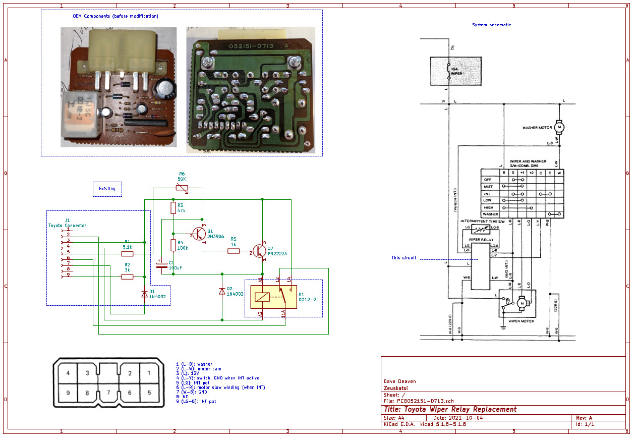
Your mid-eighties Toyota vehicle no longer has intermittent windshield wiper function. (In my case, the actual issue was simply a broken solder joint on the relay within the little green box located under the passenger side kick panel. I fixed that and went to test the module on my bench, accidentally reversed voltage, and destroyed the board entirely.)
Solution
Here's a schematic with some relevant pinouts that I replaced the board's components with. I removed most of the components from the OEM board - but you can salvage the relay (K1), two resistors in the intermittent variable resistance circuit (R1, R2), and a protection diode (D1) for the wiper motor backvoltage (and, of course, the connector J1). I made the rest on a small PCB, connected it to the right spots on the main board, and tucked it all back into the green box. Note that my design has the relay coil on ground and the switching transistor Q2 on the +12V side, so you'll also need to cut a trace on the board to disconnect the relay coil solder pad from +12V.
My truck does not have the "mist" function on the stalk, so I didn't implement that (it should run a few intermittent cycles and the washer, too... I think). But the rest works perfectly. And, you can choose the range of timing that you like for intermittent by adjusting the variable resistor R6.
One other note, in my truck there's actually a pigtail taking the connector J1 into two smaller connectors, I believe one of these is a 4-wire that only implements wiper {off, low, hi} while the other connector implements intermittent. I didn't bother figuring all of that out, but if your truck has a different configuration (I assume the admirable Toyota engineers re-used the green box part across many models) you may have sightly different connections.